Product description (expand/collapse)
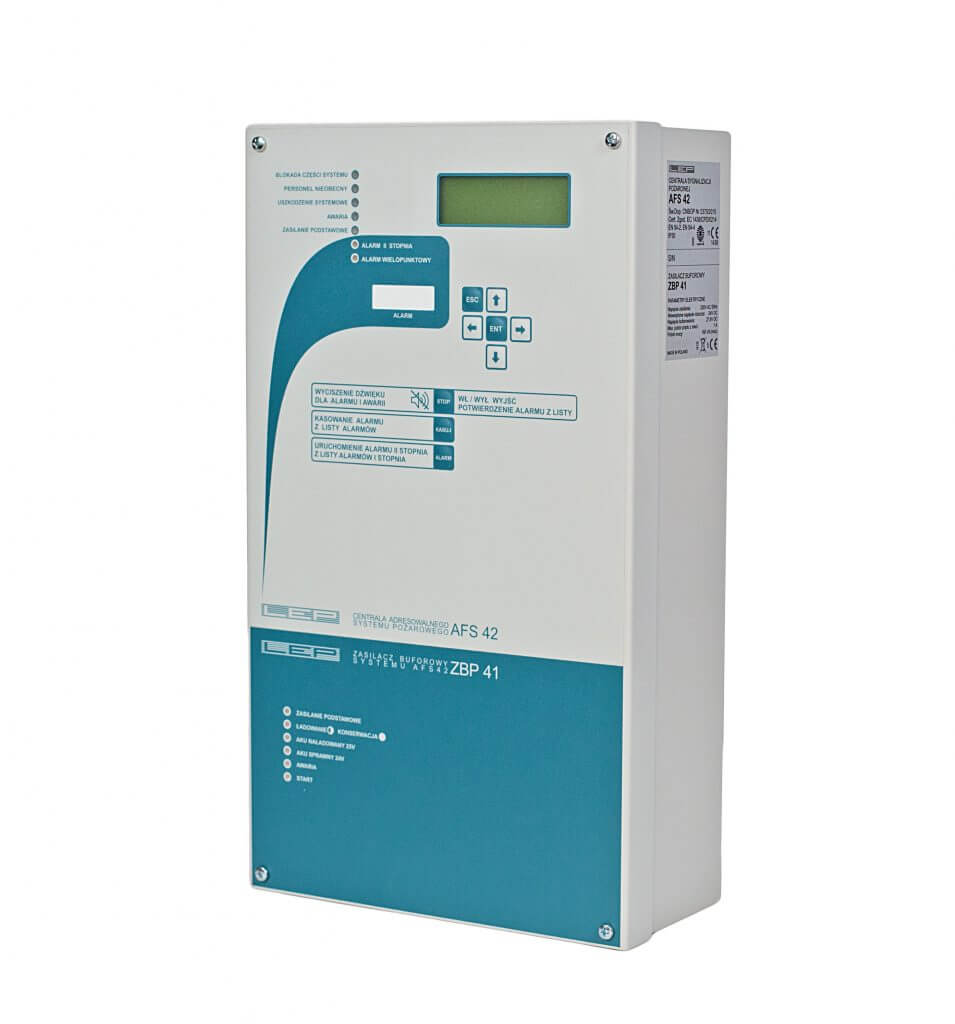
The AFS42 fire alarm control panel is the main element on the basis of which you can build a modern fire alarm system in small and medium-sized facilities. It allows for the identification of the place where the fire started and for automatic activation of actuators programmed independently.
The AFS42 fire alarm control panel was designed to build a fire alarm system adapted to a specific facility. In order to obtain the required number of addressing lines and outputs for actuators, up to five AFS42 fire control panels can be combined into one system.
It also allows for the construction of a distributed system in whichthe control panels are connected only by the RS485 network, and the rest of the connections are local within each of the control panel.The entire system is managed from one main switchboard. In order to increase the reliability, the RS485 network runs on two independent paths. Additionally, in the event of a simultaneous communication failure, the control panels switch to the independent operation mode on both lines.
The principle of operation (expand/collapse)
The work of the AFS42 fire alarm control panel is based on the execution of programs in three cooperating microprocessors – based on the configuration entered into the control panel memory by the installer. Three independent information channels are constantly monitored: the status of the detection line, the status of the power supply with the battery supplying the system and the status of the actuators. Any discrepancies between the system configuration and the actual state are immediately converted into states and alarm signals.
The control panel configuration allows for grouping addresses in the detection line into zones, setting different alarm levels for addresses and zones, for automatic switching to work without personnel, for configuring the operation of actuators and for entering text descriptions for addresses, zones and actuators. All events occurring during the system operation are saved in the non-volatile event memory, and then they can be viewed on the control panel display. The operation of the control panel microprocessors includes multi-level security systems against data loss or program freezing. The AFS42 fire alarm control panel supports one detection line in which 100 addresses can be monitored.
Fire alarm system
The system consists of five control panels, has five detection lines, 500 addresses and 20 outputs for executive devices. Looping the line allows the supervision of the entire facility to be continued despite the occurrence of a short circuit or break in the line. The AFS42 fire alarm control panel monitors the presence of detectors in the line (correct operation) and the alarm status of a given detector.
The AFS42 fire alarm control panel cooperates with OSD63A addressable smoke and heat detectors installed in the detection line and ROP42 addressable manual call points. OSD63 and ROP42 include an addressing circuit with a double-sided short-circuit isolator. By means of MAR42 addressing modules, any two-state fire alarm detectors can be used in the system, in which the alarm condition is characterized by an increase in the supply current or a short circuit in the circuit. The MAR42 module also performs the function of a sideline adapter.
Technical data (expand/collapse)
| Number of defined zones | 50 |
| Network operation possible | yes – up to 5 control panels |
| Type of conrol panel | addressable |
| Number of relay outputs | 4 |
| The maximum current of the contacts of the relays | 1A/30V DC |
| Configurable properties of the relay outputs: – NC / NO – potential / potential free – supervised / not supervised – possibility of silencing | yes / yes / yes / yes |
| Multistage alerting system | yes |
| Interdependent alerting | yes |
| Alarm counter capacity | 10 000 events |
| Real time clock | yes +/- 2s per 24h |
| Number of detection lines | 1 |
| Type of detection line | loop |
| The maximum number of elements per line | 100 |
| The maximum number of elements in a line, including the side lines | 120 |
| Maximum number of elements on a single side line | 4 |
| Detection line voltage | 20V |
| Maximum current in supervision mode | 400mA |
| APermitted effective line capacity | 100nF |
| Permitted line inductance | 0,1mH |
| Permitted line resistance | 80Ohm |
| Short-circuit isolator in the control panel output circuit | yes |
| Short circuit isolator in each line element | yes |
| Adjustable signal delays | yes |
| – waiting for alarm confirmation | from 0s to 40min every 10s |
| – recognition of the event after confirmation | from 0s to 40min every 10s |
| – delay of the alarm outputs activation | from 0s to 40min every 10s |
| Interdependent alerting | yes |
| Real time clock | yes +/- 2s per 24h |
| Recommended cable in the detection line | YnTKSYekw 1x2x0,8 |
| Detection line cable screen connection | one-sided to the control panel housing |
| Recommended signal cable | HLGs 2×1,0 |
| Earthing of the control panel housing | PE wire of the power cord |
| Connecting the screen of the RS485 transmission cable | one-sided to the control panel housing |
| Control panel firmware version/span> | AC5 AS5 |
| Weight (without batteries) | 5,4 kg |
| Dimensions (height x width x depth) | 403 x 231 x 115 mm |
Files and documents (expand/collapse)
 AFS42 with ZBP41 power supply – datasheet
 AFS42 – user manual
 AFS42 – technical information
 AFS42 v 5_57 – computer program (USB, GSM)
 AFS42 – EC certificate of conformity
 AFS42 – attachment to do certificate of conformity
 AFS42 – certificate of approval
 AFS42 – protocol of carried out tests
 AFS42 – instructions for testing


