Product description (expand/collapse)
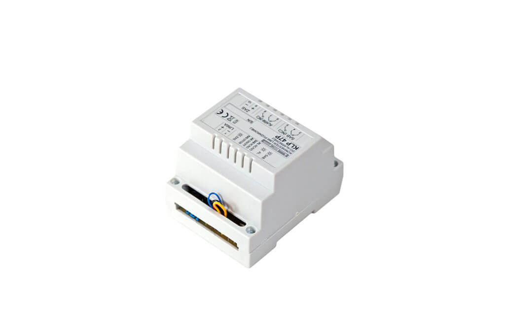
The KLP47P fire line converter (conventional lines of fire detection and alarm systems) to burglary alarm system lines allows you to connect a conventional, two-wire line with fire detectors to a six-wire fire line of the intrusion panel.
Principle of operation (expand/collapse)
The converter has two relays switched under the influence of the detector alarm signal and the tamper signal (line break, detector removal from the socket). Switches for relay operating status (NC/NO) and operating modes are available in the form of extended wire loops in different colors (“jumpers”). Factory settings of the device: all jumpers closed (tamper function enabled, relays in NC mode, autoreset function enabled, first alarm reset function disabled).
The figure shows the state of the relay contacts for the factory settings of the device after powering up in the quiescent state: 3 out of 4 and 6 out of 7 are shorted, respectively.
An alarm of any detector will cause: the AL indicator will flash approximately every 6 seconds and the ALARM relay contacts will switch (7 and 8 closed) – this is an “alarm” signal for the burglary control panel.
Interruption of the detection line will cause the AL indicator to switch on and the SAB relay to switch (4 and 5 shorted) – this is a “sabotage” signal for the burglary control panel.
The detection line has a short-circuit protection – a short-circuit in the line is signaled by the AL indicator flashing, the ALARM relay switching (7 and 8 closed), the SAB indicator lighting up and the SAB relay switching (4 and 5 closed). Opening the red jumper (autoreset) causes the alarm state to latch: (7 and 8 closed) and the AL indicator is lit continuously until the device power is turned off.
The yellow and blue jumpers change the operating mode of the signaling relays from NC (closed – factory state) to NO (open).
Opening the black jumper activates the reset function – cancellation of the first alarm from the detector (invalidation of accidental alarms from detectors).
In the detection line (terminals 1 and 2 LINE) max. 50 OSD23 detectors with GNP18 sockets, while the alarm can occur simultaneously in up to 12 detectors.
The detection line must be terminated with a 2.7kΩ terminating resistor installed in the last slot in the detection line.
Technical data (expand/collapse)
| Supply voltage | 12V DC |
| Maximum current consumption | |
| -in a surveillance state | 40mA for 2xNC 15mA for 2xNO |
| -in the alarm state | 160mA |
| Relay contacts load capacity | 24V/1A (125V/0,5A) |
| Controls | green – device power supply |
| red – alarm status in the detection line | |
| yellow – tamper in the detection line | |
| Jumpers | yellow – operating state of the SAB relay (closed: NC, open: NO) |
| blue – AL relay operating status (closed: NC, open: NO) | |
| red – auto-reset (closed: detection line auto-reset, open: alarm latch) | |
| black – reset function (closed: reset function disabled, open: cancellation of the first alarm from the detector) | |
| Operating temperature range | -25° C to +55° C |
| Relative humidity | to 80% at +40°C |
| Weight | 100g |
| Dimensions | 90 x 105x 70 mm |


